WSPR TV User Guide
WSPR TV is an open-source telemetry viewer for several WSPR-based protocols. While the user interface is designed to be as intuitive as possible, this guide explains some of the site's more advanced features.
Returning to This Page
If you ever forget something and need to return to this page, the band
selection menu in the control panel (where you specify the HF band) has
a User Guide option at the top.
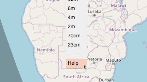
There are several other links in the band menu:
History-- displays recently viewed telemetry.Channel Map-- shows activity on U4B channels.CT Wizard-- opens the U4B Custom Telemetry Wizard.
Additionally, a small WSPR TV link next to the OSM attribution in the bottom-right corner of the screen links to the project's GitHub repository.
Control Panel
The control panel in the top-left corner of the screen contains most of the parameters for telemetry visualization.
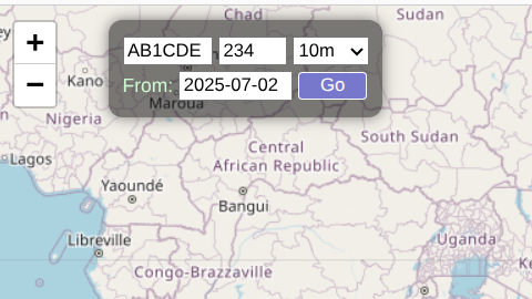
Callsign
This is typically a 4-6 character callsign such as AB1CDE. However,
for protocols that use a combination of type 2 / type 3 WSPR messages
(see below), a suffix or a prefix can also be specified: P/AB1CDE or
AB1CDE/S.
Channel
This field encodes both the protocol and the channel identifier. The following formats are supported:
-
U4B [
<CH>]. U4B is a commonly used telemetry protocol that encodes 6-character Maidenhead grid location, altitude, speed, voltage, and temperature through a pair of sequential type 1 WSPR messages. The first message is a "regular" callsign message, while the second message uses unallocated callsign space starting withQ,0, or1.<CH>is a number between 0 and 599 representing the first and third characters of the special callsign, the starting minute, and one of 4 frequency "lanes".Example:
459on the 10m band indicates transmissions that use Q*2* special callsigns, begin 2 minutes into the 10-minute cycle, and transmit in the last 40 Hz of the band.Additional special callsign messages may follow in slots 2-4, representing custom telemetry (CT). Custom telemetry is discussed in detail below.
U4B channels are allowed to have a
V<variant>suffix, such as321V100, to enable certain experimental extensions. They can also have aP<num>suffix, to display certain Custom Telemetry without specifying the usual URL decorators (e.g. use<ch>p10to view Nomad's enhanced CT). -
U4B [
U<CS1><CS3><M>]. This is an alternative U4B channel representation that specifies the first and third characters of the special callsign (<CS1>and<CS3>) as well as the starting minute (<M>) explicitly. Unlike the numeric channel format, this representation does not include frequency lane information.Example:
UQ22corresponds to channel 459 (and also 454, 449, etc.) on the 10-meter band. It indicates Q*2* special callsigns and a starting minute of 2. -
Generic 1 [
g<M>]. This is the simplest type of telemetry, consisting of a single type 1 WSPR message. Location is indicated by a 4-character Maidenhead grid locator and provides ~70x100 mi spatial resolution. No other attributes, such as altitude or speed, are encoded.<M>is the starting minute (must be one of 0, 2, 4, 6, or 8).Example:
g2if transmissions begin 2 minutes into the 10-minute cycle. -
Zachtek 1 [
z<M>]. This is an older Zachtek protocol that is similar toGeneric 1but also coarsely encodes altitude in the WSPR message's power field (resolution ~1 km).Example:
z8. -
Generic 2 [
G<M>]. This encoding uses a pair of type 2 / type 3 WSPR messages. The first message encodes a compound callsign, while the second message adds a 6-character Maidenhead grid locator, improving spatial resolution to ~3x4 mi. No other attributes are encoded. Both messages must be received for a spot to be decoded.<M>is the starting minute (must be one of 0, 2, 4, 6, or 8).Example:
G4if the first (type 2) message is transmitted 4 minutes into the 10-minute cycle. -
Zachtek 2 [
Z<M>]. A newer Zachtek protocol that is similar toGeneric 2. The power fields of both WSPR messages are used to encode the altitude to a resolution of ~60 m.Example:
Z6. -
WB8ELK [
W<CS1><CS3><M>]. Transmitted via a pair of type 1 messages. The second message uses specialQ/0/1callsigns similar toU4B, although the encoding is completely different. Provides altitude to ~60 m resolution, voltage, and approximate number of GPS satellites (not displayed by WSPR TV). Location is a 6-character Maidenhead grid locator (~3x4 mi resolution).<CS1>and<CS3>are the first and third characters of the special callsign.<M>is the starting minute (must be one of 0, 2, 4, 6, or 8).Example:
WQ46if Q*4* special callsigns are used and transmissions begin 6 minutes into the 10-minute cycle.
If the channel field is empty, all regular callsign messages are displayed. The callsign may be compound. Spots are shown without filtering in this mode, and no line segments between markers are drawn.
For new designs, prefer the U4B protocol. Not only is it well-documented and capable of packing more values into two sequential WSPR messages, but it also correctly reports TX power in the regular callsign transmission (this data is used in radio propagation studies).
Band
Specifies the frequency band for WSPR transmissions. There may be additional, band-unrelated options at the start of this menu, such as a link to this user guide.
Start Date
The start date should be in the YYYY-mm-dd format,
such as 2025-07-15. This field defaults to 30 days before today and is
a good choice for minimizing the load on WSPR Live servers and making
the WSPR TV user interface more responsive. The start date normally cannot
be more than a year before the end date (specified via a URL parameter, see
below). For historical telemetry, you can specify a start date over a
year ago by appending the appropriate end_date parameter to the URL.
The "From:" label (to the right of the start date field) is a link to the History page.
URL Parameters
Because WSPR TV is optimized for use on mobile devices with small
screens, the control panel includes only the most commonly used
telemetry parameters. Additional parameters may be specified by
appending them to the URL using the param1=value1¶m2=value2
format.
-
end_date=
<YYYY-mm-dd>specifies the end date (up to 23:59:59) for a track.end_datedefaults to today and cannot be less thanstart_dateor more than a year afterstart_date, unlessate1yis also present. -
ate1y (abbreviation for "allow tracks exceeding 1 year", no value needed) allows tracks to be up to 2 years long. Use this parameter only when absolutely necessary.
-
time=
<utc|local>causes timestamps to be displayed in UTC or local timezone (default). There are other ways to change time display in WSPR TV (see below). -
units=
<metric|imperial>specifies the display units. There are other ways to switch units in WSPR TV (see below). -
detail=
<0|1>controls the amount of detail shown in the data view. -
noupdate (no value needed) instructs WSPR TV not to update the track every 10 minutes.
noupdateis implied ifend_dateis in the past. Adding this parameter may make sense when sharing WSPR TV links widely to minimize the additional load on WSPR Live servers. -
nomirror (no value needed) disables mirroring of the track across the antimeridian. Use this parameter if the UI becomes sluggish because of too many spots.
-
detach_grid4 (no value needed) removes low-resolution (grid4) spots from the track. Removed spots can still be seen in the data table and on the map with
show_unattached. -
detach_noct (no value needed) removes spots that have no Custom Telemetry from the track. Removed spots can still be seen in the data table and on the map with
show_unattached. -
min_match=
<score>specifies the minimum co-reception match score needed to link U4B telemetry. Defaults to 1. Setting the score to 0 disables co-reception matching. -
show_unattached (no value needed) causes WSPR TV to display spots that are not attached to the track.
-
sun_elev=
<degrees>displays a solar isoline on the map that corresponds to the solar elevation. This is useful for estimating when a balloon may start or stop transmitting, assuming its location is approximately known. See more below.
The callsign, channel, start date, and band can be specified as URL
parameters as well (using cs, ch, start_date, and band
respectively) and will pre-fill the control panel parameters. Example:
cs=AB1CDE&ch=321&band=10m&start_date=2025-07-15.
Custom-telemetry-related URL parameters ct_dec, ct_labels,
ct_llabels, and ct_units are discussed in the
Custom Telemetry section of this guide.
Map View
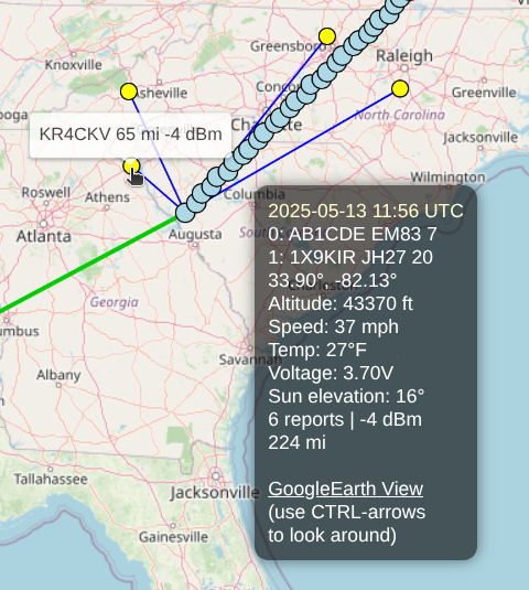
A track is rendered as a sequence of small white grid4 markers (low resolution) and larger light blue grid6 markers (high resolution). Enhanced U4B telemetry spots (see below) are shaded in a darker blue. Markers are connected by green lines.
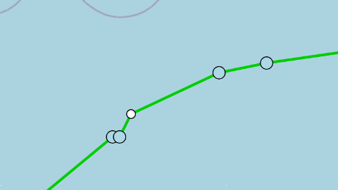
Note that some spots may be unattached (i.e., not shown as part of the track) for one of the following reasons:
- A U4B spot has the
gps_validbit set to 0. If shown on the map, these spots are colored light red. - A grid4 (low-resolution) spot is located near a grid6 (high-resolution) spot.
- A spot has unusual characteristics, such as an improbable location relative to adjacent spots.
- The channel field is blank (unknown telemetry protocol).
Unattached spots are always displayed in the data view. They are also
shown on the map when the show_unattached
URL parameter is set.

The Equator is shown as a grey horizontal line. The first spot in the
track (after start_date) is green, while the last one is red. Night /
day regions are indicated on the map by grey shading.
Spot Info
Hovering over a spot (or touching it on a mobile device) brings up the Spot Info panel. This displays most of the available telemetry, including raw WSPR messages, reception statistics, and up to 8 custom telemetry values.
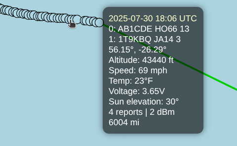
Clicking on a spot (vs. hovering) also opens the Spot Info panel, but now the panel remains open when you move away from the spot, and additional information is displayed:
-
A Google Earth link to see "what the balloon is seeing", with the camera positioned at the correct latitude, longitude, and altitude, and facing East. Once in Google Earth, holding
CTRLwhile pressing the arrow keys (left, right, etc.) allows you to "look around" without moving the position of the camera. -
RX stations, shown as yellow dots and connected by blue lines. When hovering over an RX marker, the callsign of the receiving station, distance, and signal strength are shown.
To close the Spot Info panel, click or touch anywhere on the map outside of a marker.
Flight Synopsis
A summary of telemetry is displayed in the control panel below the
parameter fields. These should be self-explanatory. The track updates
automatically every 10 minutes (unless end_date is in the past or the
noupdate URL parameter was used), and the time of the next update is shown
in light yellow.
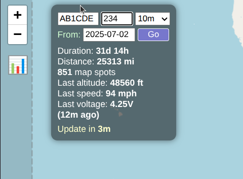
Some of the values in the Flight Synopsis also serve as toggles --
clicking on the distance, altitude, or speed (e.g. 25313 mi in
the example above) switches units from imperial to metric or vice
versa. Clicking on (12m ago) in the example above toggles UTC time
display. These preferences will be remembered if you return to the page
later.
Allowing the map to update itself is by far the most efficient way to view real-time data. Do not refresh the page via the browser -- doing so results in considerably more load on WSPR Live servers. Periodic updates are already timed to occur at the optimal time -- roughly 75 seconds after the last message in a TX sequence is received (it takes some time for WSPR messages to trickle into the WSPR Live database).
Auxiliary Info
Clicking anywhere on the map outside of a marker brings up the Auxiliary Info bar in the bottom-left corner of the screen.
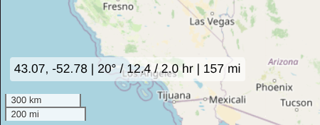
The displayed values include:
- The latitude and longitude of the clicked location (43.07, -52.78 in the example above)
- Current sun elevation at the clicked spot (20°)
- Time since sunrise at the clicked spot (12.4 hours, can be negative during the night)
- Time until sunset at the clicked spot (2.0 hours, can be negative during the night)
- If a track marker was already selected, the great circle distance between that marker and the clicked spot (157 miles)
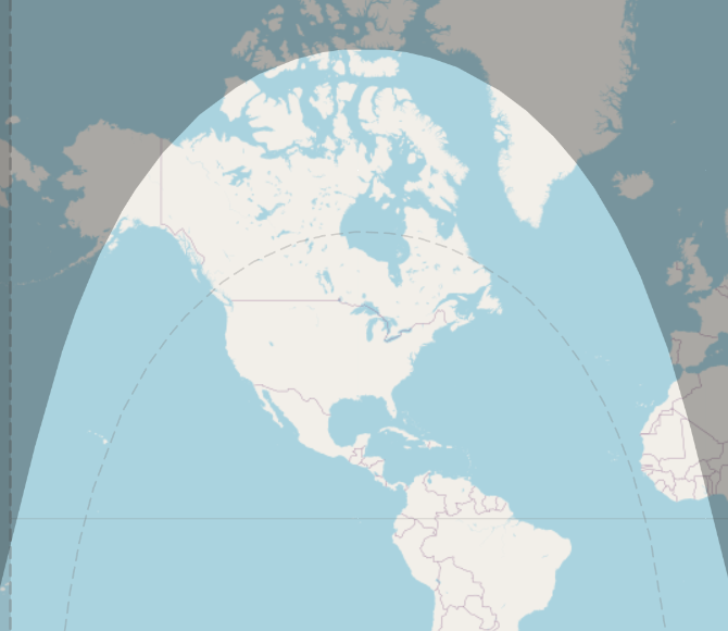
Solar Isoline
A dotted line marks the region where the Sun's elevation exceeds a certain
value. This value can be set using the
sun_elev URL parameter or computed automatically from
recent flight data as the lowest Sun angle at which transmissions
occurred. To disable this feature, add sun_elev=off to the URL.
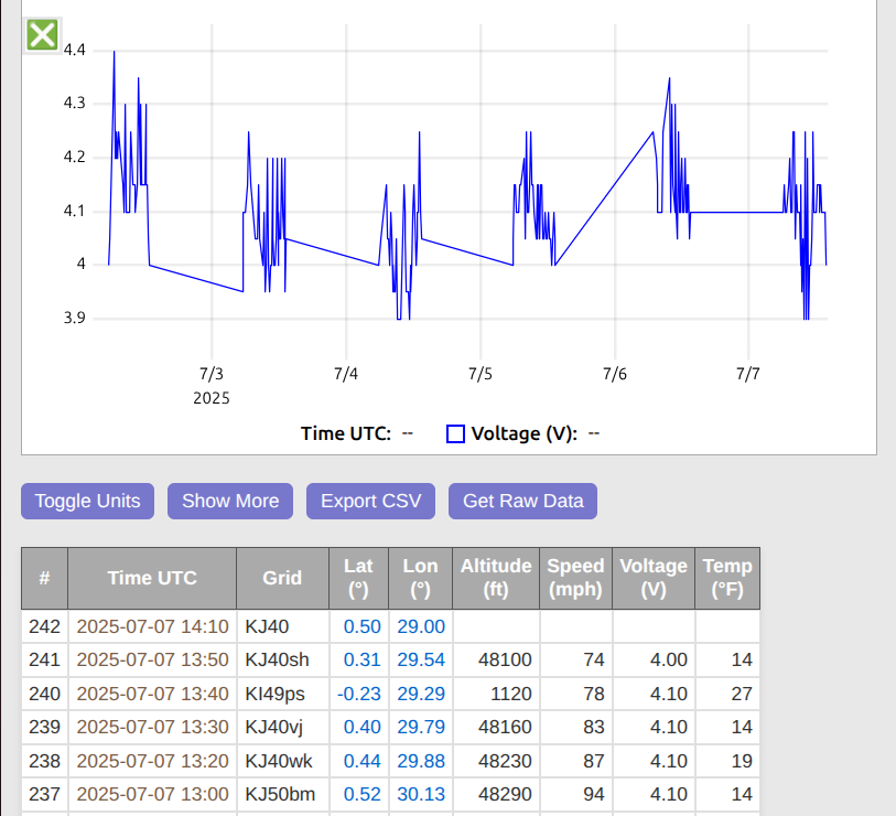
Data View
Clicking on the chart icon (in the top-left corner, below the map zoom buttons) will close the map view and open the data view. The data view contains:
- A variety of charts for all tracked telemetry values, including custom telemetry.
- A table showing all received spots, including grid4 spots not displayed on the map.
- Buttons to export spots as a CSV table, all raw data as a JSON file, and to switch units and time format (from UTC to local).
- A button to display / graph more data, such as computed speed and vertical speed.
To return to the map view, click on the X icon in the top-right corner
of the screen.
The map will continue to update every 10 minutes while the data view is open, but the data view currently does not update periodically. To see fresh values, switch to the map view and then back to the data view.
Chart Controls
The charts are interactive and can be zoomed in and out:
- To zoom in on the X-axis: click on a starting point and then drag left or right (without changing the Y position by more than 20 pixels). You will see a horizontal slice of the chart being selected.
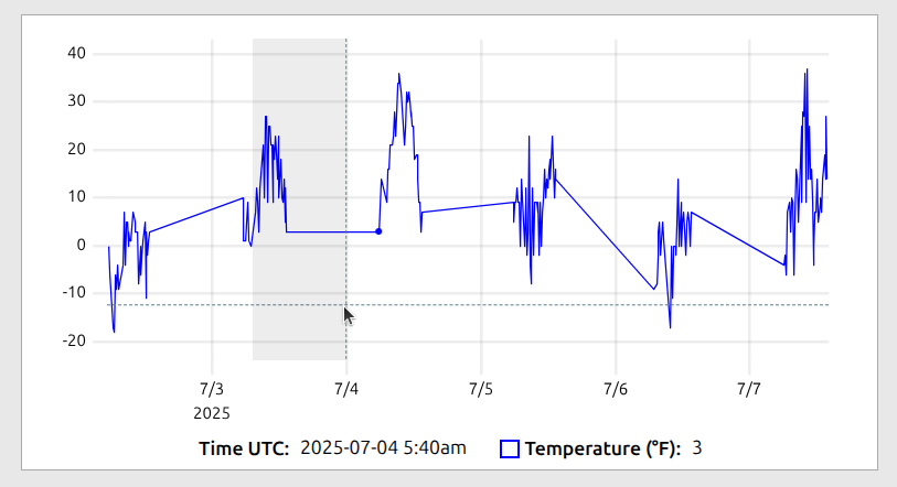
- To zoom in on the Y-axis: click on a starting point and then drag up or down (without changing the X position by more than 20 pixels). You will see a vertical slice of the chart being selected.
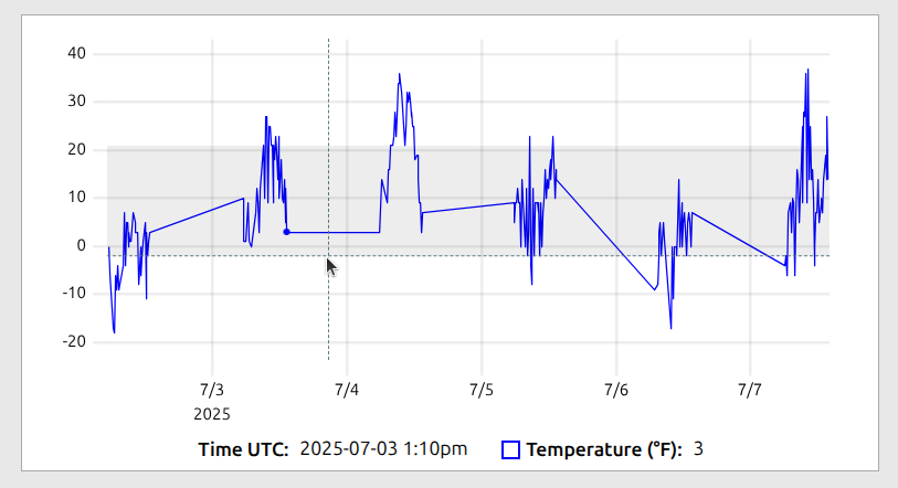
- If you click and drag left or right, and then drag up or down by more than 20 pixels (while still clicking), a rectangular area of the chart will be highlighted. If you selected a rectangular area by mistake, drag to minimize the unwanted dimension to 0; this will revert the selection to either a horizontal or vertical slice.
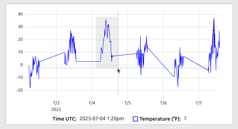
- To zoom out to the original (full) view, double click anywhere on the chart.
On mobile devices, charts support touch gestures such as drag-to-pan and pinch-to-zoom.
Telemetry Detail
By default, only the core telemetry values are shown in the data view
(e.g., speed, altitude, temperature, and voltage for U4B). The
Show More button can graph / display several additional fields:
-
Computed values, such as computed speed (based on location changes over time) and vertical speed (i.e., rate of ascent / descent). These may not be available for every spot, due to computational uncertainty. Moving from one 6-character grid to the next can mean covering a distance of 0.1 miles or 7.9 miles. For this reason, waiting until the location has changed over several grids can be necessary for reasonably accurate (+/- ~10%) speed estimates.
-
RX statistics, such as the number of receiving stations for each spot, maximum SNR, and maximum RX distance.
-
The TX power field reported by WSPR, but only for the U4B protocol and only if the values differ from spot to spot.
Telemetry detail can also be set with the detail
URL parameter.
Time Display
The Toggle UTC button switches time display from UTC to local (local
here refers to your device's timezone, not the balloon's location).
The preference affects all displayed, charted, and CSV exported values
in both the map and data views, and is remembered across browser sessions.
Another way to toggle time display is to click on the (X ago) value in
the control panel of the map view.
Unit Conversion
The Toggle Units button switches units from metric to imperial and
vice versa. The preference affects all displayed, charted, and CSV
exported values in both the map and data views, and is remembered across
browser sessions.
Custom telemetry units are opaque to WSPR TV and are not impacted by unit conversion.
Another way to switch units is to click on the Distance, Speed, or
Altitude values in the control panel of the map view.
Data Export
The Export CSV button exports the data view table exactly as it is
displayed (in currently selected units, in the same field order, etc).
The Get Raw Data button returns the entire telemetry dataset as a
tree-like JSON object. This includes raw WSPR messages and per-spot RX
information.
Example of a raw record:
{ "slots":[
     {"ts":"2025-06-02T05:06:00.000Z",
      "cs":"AB1CDE",
      "grid":"JL88",
      "power":7,
      "rx":[{"cs":"DK6UG","grid":"JN49cm","freq":28126141,"snr":-21} ...]},
     ...more slots],
  "ts":"2025-06-02T05:06:00.000Z",
  "grid":"JL88mt",
  "speed":51.856,  // in km/h
  "voltage":3.7, // in V
  "temp":-6,  // in C
  "altitude":13560,  // in meters
  "lat":28.8125,
  "lon":17.041
}
Raw data is always exported in metric units and does not depend on the current unit selection.
The format of raw records may change in future versions of WSPR TV.
U4B Custom Telemetry (CT)
The U4B protocol includes a provision for transmitting custom
telemetry as additional Q/0/1 messages. The informational content of
each WSPR message is first converted to a so-called BigNumber -- a
value ranging from 0 to 389,512,281,599 (approximately ~38.5 bits). The
least significant bit of this message (HdrTelemetryType) is set to 1
for standard U4B telemetry and 0 for custom telemetry. As a result,
custom telemetry messages provide approximately 37.5 bits of raw
payload.
In Custom Telemetry (CT), BigNumber contains a single header
after HdrTelemetryType -- HdrSlot -- followed by an opaque
vendor-defined value:
[HdrTelemetryType] - 2 values, always 0 for custom telemetry
[HdrSlot] - 5 values, used to minimize interference between adjacent U4B channels
[OpaqueData] - around ~35.2 bits of payload
HdrTelemetryType is the least significant bit of BigNumber.
CT Encoding
This section is intended for U4B firmware developers.
To remain compatible with ET0, custom telemetry BigNumber values are
converted to special callsign WSPR messages differently than before. If v is
BigNumber with its least significant bit (HdrTelemetryType) removed,
the following transformation of v is needed before BigNumber is converted
to a WSPR message:
v = (v / 320) * 320 + (v % 5) * 64 + ((v / 5) % 64)
This transformation effectively moves ET0's HdrSlot header from the beginning of
BigNumber to the middle, where it used to be before Custom Telemetry was introduced.
CT Encoding Example:
Suppose you want to send 3 values -- v1, v2, and v3 -- using a CT message. Let's say the maximum number of values for each is
v1_size = 4000;
v2_size = 4000;
v3_size = 2000;
Together this is slightly less than 35 bits, so the values fit into a CT message.
The values can be loaded into BigNumber with multiplication and addition,
starting with the last value:
uint64_t v = 0;
v = v * v3_size + v3;
v = v * v2_size + v2;
v = v * v1_size + v1;
For CT, we also need to add HdrSlot and HdrTelemetryType.
Let's say you want to send your message in slot 2:
hdr_slot = 2;
hdr_slot_size = 5;
v = v * hdr_slot_size + hdr_slot;
v = v << 1;  // add HdrTelemetryType = 0
Our BigNumber is now ready to be sent over the air:
SendBigNumber(v);
With the introduction of CT, standard and custom telemetry messages
are encoded from BigNumber differently:
void SendBigNumber(uint64_t v) {
  if ((v % 2) == 0) {
    // Custom telemetry
    v = v >> 1;  // temporarily discard HdrTelemetryType
    v = (v / 320) * 320 + (v % 5) * 64 + ((v / 5) % 64);
    v = v << 1;  // add HdrTelemetryType back
  }
  uint32_t m = v / 615600;
  uint32_t n = v % 615600;

  uint64_t wspr_message = CreateWSPRMessage(m, n);
  SendWSPRMessage(wspr_message);
}
If a CT-compatible tracker also supports ET0, the order of ET0 headers
packed into BigNumber should be
[HdrTelemetryType][HdrSlot][HdrRESERVED][HdrType], and NOT the previous
[HdrTelemetryType][HdrRESERVED][HdrType][HdrSlot]. The two transformations --
rearranging of values in BigNumber as shown in the SendBigNumber function
above and reshuffling of ET0 headers -- cancel each other out, allowing the
wire format of ET0 telemetry to remain exactly the same.
CT Decoding
This section is intended for U4B developers.
A CT-compatible decoder should compute BigNumber from m and n
as shown below:
void ComputeBigNumber(uint32_t m, uint32_t n) {
  uint64 v = m * 615600ULL + n;
  if ((v % 2) == 0) {
    // Custom telemetry
    v = v >> 1;  // temporarily discard HdrTelemetryType
    v = (v / 320) * 320 + (v % 64) * 5 + ((v / 64) % 5);
    v = v << 1;  // add HdrTelemetryType back
  }
  return v;
}
If a CT-compatible decoder also supports ET0, the order of ET0 headers
in BigNumber should be interpreted as
[HdrTelemetryType][HdrSlot][HdrRESERVED][HdrType], and NOT the previous
[HdrTelemetryType][HdrRESERVED][HdrType][HdrSlot].
There are no changes in how m and n are computed from special-callsign WSPR
messages.
ET0
ET0 is a subtype of CT,
because it also starts with HdrSlot (assuming that BigNumber was
decoded in a CT-compliant manner). ET0 has the following
structure:
[HdrTelemetryType] - 2 values, always 0 for custom telemetry
[HdrSlot] - 5 values, used to minimize interference between adjacent U4B channels
-- CT OpaqueData starts here --
[HdrRESERVED] - 4 values, set to 0 (used as the protocol version number)
[HdrType] - 16 values, of which only 0 (USER_DEFINED) and 15 (VENDOR_DEFINED) are specified
[HdrType-dependent data] - around ~29.2 bits of payload
Value Packing / Unpacking
First, let’s review how values are packed into a message. To append a value in the range [0, n), we multiply the existing message by n, then add the new value. The multiplication shifts the current message left, creating space, while the addition inserts the new value at the end.
The inverse process -- unpacking -- uses division and modulus. The modulus (i.e., the remainder from division) extracts the value from the end of the message, while the division shifts the message right, effectively removing the extracted value.
As an example, suppose a message ends with three packed fields:
value3, value5, and value7, which respectively hold 3, 5, and 7
values.
To unpack value3, we first shift the message right by dividing it by
5 * 7, which removes value5 and value7, and moves value3 to the end.
Then, we apply a modulus of 3 (i.e., take the remainder after dividing
by 3) to extract the value of value3.
Value Types
Custom telemetry values can be opaque or native. Opaque values can be graphed and displayed in a table, but their meaning is otherwise not known to WSPR TV. By contrast, native values have a well-defined type, and can influence the site's function at a more fundamental level.
Resolution / Range Enhancers
Currently, 10 enhanced telemetry resolution / range types are supported:
- Type 100: enhanced longitude resolution
- Type 101: enhanced latitude resolution
- Type 102: enhanced altitude resolution
- Type 103: enhanced altitude range
- Type 104: enhanced temperature resolution
- Type 105: enhanced temperature range
- Type 106: enhanced voltage resolution
- Type 107: enhanced voltage range
- Type 108: enhanced speed resolution
- Type 109: enhanced speed range
These types increase the resolution or range of standard (grid6) U4B telemetry. The additional resolution / range depend on the size of the corresponding custom telemetry fields. For example, if 10 values are allocated to type 102, altitude resolution improves by a factor of 10, from 20m to 2m. If 3 values are allocated to type 103, altitude range increases by a factor of 3, from 0 - 21360 meters to 0 - 64080 meters.
Temperature range and voltage range are special in that they extend in both directions, above the maximum value and below the minimum one. The direction alternates as the value of the range increases. For example, when type 107 (enhanced voltage range) value is 1, the range spans 5 - 7V. When the value is 2, the range becomes 1 - 3V. Other ranges, such as speed and altitude, grow in the positive direction only.
Setters
- Type 120: time offset (seconds)
- Type 121: longitude
- Type 122: latitude
- Type 123: grid4 longitude resolution
- Type 124: grid4 latitude resolution
- Type 125: altitude
- Type 126: temperature
- Type 127: voltage
- Type 128: speed
These types can set / override various spot attributes. Longitude / latitude
setters subdivide a geographical area (grid4 or the entire world), while
other types use first_value and step attributes similar to opaque types.
Other
- Type 140: new spot
- Type 141: switch to
- Type 142: alias to
Type 140 creates a new spot (empty, with only the timestamp inherited from the parent spot), while type 141 switches to another previously created spot. Switching may be necessary to specify which spot a subsequent type applies to. By default, new CT messages modify the original (parent) spot.
Both of these types take a single attribute -- a user-chosen spot id.
Type 142, aliasing, allows one opaque type to be aliased to another, so that they can both be shown in the same column of the data table and on the same graph, even though they come from different CT messages. The parameter to type 142 is the index of the previously defined opaque type (starting from 0).
Custom Telemetry Message Definition
WSPR TV has an extremely flexible custom telemetry definition
mechanism that is able to decode CT, ET0, or any past or
future protocols that pack values into contiguous (but possibly fractional)
bits of the U4B BigNumber.
More precisely, WSPR TV operates on BigNumber / 2, with the least
significant bit (HdrTelemetryType) removed since it is always 0. When
BigNumber is mentioned later in this section, it will always be this
truncated, 37.5 bit version.
The basic building block of WSPR TV's custom telemetry specification is the message definition. A message definition includes:
- A set of filters that define the conditions a message must meet in order to be decoded.
- A set of extractors that specify how individual values should be
extracted from
BigNumber, linearly transformed, and annotated.
Filter Specification
All filters in a message definition must pass for value extraction to
happen. Filters normally express conditions on snippets of BigNumber,
which are usually headers or message type selectors. For example, in the
ET0 protocol, the following conditions should be true for a message to
be accepted:
HdrSlot(5 values) is set to the slot in which the ET message was receivedHdrRESERVED(4 values) is set to 0HdrType(16 values) is set to the desired type (e.g., 0 forUSER_DEFINED)
The basic filter definition in WSPR TV is the tuple
(divisor, modulus, expected_value)
expressing the following condition:
(BigNumber / divisor) % modulus = expected_value
To support CT, a special variable slot is available to represent
the TX slot in which the custom telemetry message was received. This
allows us to express the filter set for ET0 as follows:
(BigNumber / 1) % 5 = slot
(BigNumber / 5) % 4 = 0
(BigNumber / 20) % 16 = 0
To explain, we first check that the truncated BigNumber (here again we
refer to our version of BigNumber with the HdrTelemetryType bit
removed) was received in the correct slot. To do this, we divide
BigNumber by 1 and then extract the 5 possible values of
HdrSlot field using a modulus of 5. This value has to be equal to
the special variable slot.
We then access the adjacent HdrRESERVED field by dividing BigNumber by 5
(this skips over HdrSlot) and extracting the 4 possible values
using a modulus of 4. This value also has to be equal to 0 (for
ET0).
Finally, we check that HdrType is equal to 0. We skip over both the HdrSlot
and HdrRESERVED fields, hence the division is by 5 * 4 = 20. We use a modulus
of 16 to extract the 16 possible values. This value also has to be equal to 0 (for
USER_DEFINED).
If the divisor in a filter tuple is missing, it is implied to equal
the previous divisor multiplied by the previous modulus.
In other words, the divisor is set to the end of the previous filter
field. If no initial divisor is specified anywhere, the
first divisor starts at 1 for unspecified protocols and at
the end of the headers for known protocols (e.g., initial_divisor = 5
when one of the filters in the message definition is ct).
Temporal Filters
WSPR TV provides a powerful mechanism for multiplexing multiple message
types within the same slot -- without using any extra bits to indicate
which schema is in use -- via the ts variable.
ts represents the Unix timestamp (in seconds since epoch) for the
preceding regular callsign transmission.
This variable can be used instead of BigNumber in filters:
(ts / divisor) % modulus = expected_value
This allows WSPR TV to decode messages differently based on transmission time -- for example, every other transmission, during odd-numbered hours, or on even-numbered days. Multiple message types can be multiplexed into the same CT slot.
Another time-dependent filter uses the variable slot and expresses the
condition:
slot = value
This enables different handling of messages in, for example, slot 2 versus slot 3.
Opaque Value Extraction
Once all filters in a message definition pass, a set of values are extracted. Generally, extraction is specified using the following tuple of parameters:
(divisor, modulus, start_value, step)
divisor and modulus here specify how to extract the raw value from
BigNum, while start_value and step are used to linearly transform the
raw value into its decoded form:
raw_value = (BigNumber / divisor) % modulus
value = start_value + raw_value * step
As an example, suppose an ET0 message has 110 values of Pressure in
its least significant bits, and then 90 values of Heading immediately
after. Pressure starts at 0.1 and increments 0.001 Bar with every step,
while Heading starts at 0 and increments by 4 degrees. These values
can then be extracted as follows:
[divisor, modulus, start_value, step]

(320, 110, 0.1, 0.001)
(35200, 90, 0, 4)
The divisor here starts at 320 because we need to skip over the ET0
header (which has 320 values). 35200 is 320 * 110 -- we are skipping
over both the header and the Pressure value.
Because extracted values are often contiguous, a simplified 3-term extractor specification is also available:
(modulus, start_value, step)
The divisor here is implied by taking the previous divisor and
multiplying it by the modulus of the previous extractor. In other words,
the divisor is set to the end of the previous value. If no initial
divisor is specified anywhere (i.e., all extractors are 3-term), the
first divisor starts at the end of custom filters. If no custom filters
are specified, the first divisor is 1 for unspecified protocols and at
the end of the headers for known protocols (e.g., initial_divisor = 320
when one of the filters in the message definition is et0).
For the previous Pressure / Heading example, the extractor specification becomes:
[modulus, start_value, step]

(110, 0.1, 0.001)
(90, 0, 4)
Value Annotation
Extracted values can optionally be annotated with a short label, long label, and units:
-
Short label is a brief, descriptive identifier -- e.g.,
VSpeedfor "Vertical Speed". It can be up to 32 characters long and may only contain alphanumeric characters, spaces,#, and_. Short labels are shown in space-constrained areas, such as Spot Info panels and table headers. If not specified, they default toCT0,CT1, etc. -
Long label is a full descriptive name, such as
Vertical Speed. It can be up to 64 characters long and may only contain alphanumeric characters, spaces, and the characters#and_. Long labels are shown where more space is available, such as in chart legends. If not specified, long labels default to short labels, or toCT0,CT1, etc. if short labels are also missing. -
Units indicate the measurement associated with a value (e.g.
135 km/h). The leading space in units is preserved (e.g. to specify9 Vvs.9V). Units can be up to 8 characters long and may only contain letters, spaces, and the characters/and°. Countable values often don't require units:NumSats: 5is typically clearer thanNumSats: 5 sats.
Native Value Extraction
Native value extraction is specified using the following tuple of parameters:
(divisor, modulus, type_id)
Note that there is no start_value, step, or value annotation, since the type of the value is already known to WSPR TV.
When the divisor is implied, a simplified 2-term extractor specification is also available:
(modulus, type_id)
Custom Telemetry Wizard
WSPR TV provides a wizard to create new custom telemetry specifications or to import existing ones from other formats.
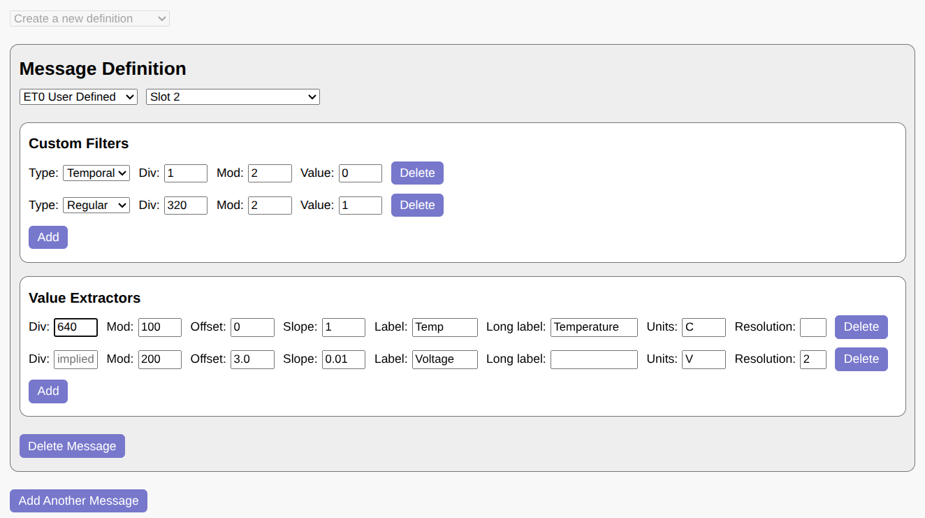
In this example, a single message is defined based on ET0 in slot 2. Two additional filters are applied: a temporal filter, which restricts the message to even slots, and a custom selector, which checks that the first bit after the ET0 header is 1 (perhaps because the message format changes when the bit is 0).
The message contains two values -- Temperature and Voltage -- which follow immediately after the selector bit. The first divisor is 640, accounting for the ET0 header (320 values) plus the selector bit (2 values). The second divisor is implied from the location of the previous field; if specified explicitly, it would be 640 * 100 = 64000.
Note that if not for the selector bit, the first divisor could be left blank as well. It would then default to 320, or the end of the headers for the ET0 protocol.
When you click "Generate URL", WSPR TV displays a preview of how the extracted values will appear:
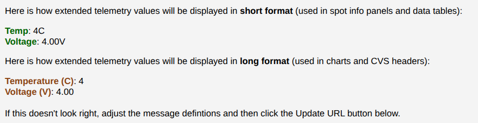
You can create as many message definitions as needed, as long as the total number of extractors does not exceed 32. Once your message definitions are finalized, click "Generate URL" to create the WSPR TV link for your custom telemetry specification.
Custom Telemetry URL Parameters
While most custom telemetry definitions should be generated using the ET Wizard, it can be useful to understand how custom telemetry URL parameters are constructed from a specification.
The ct_dec URL parameters consists of one or more decoders,
separated by the ~ character:
ct_dec=<decoder1_spec>~<decoder2_spec>~...
Each decoder in turn consists of zero or more filters and one or more
extractors. The filters are separated from the extractors with
underscores (_), whereas individual filters and extractors are
separated from each other with commas (,):
decoder_spec: <filter1>,<filter2>..._<extractor1>,<extractor2>...
A filter can have one of the following forms:
<divisor>:<modulus>:<expected_value>
<modulus>:<expected_value>  (implied divisor)
s:<slot>
<divisor>:<modulus>:<expected_value>:ts
<modulus>:<expected_value>:ts (implied divisor)
with the latter two representing temporal conditions. Shortcuts for CT and ET0 user-defined telemetry are available:
ct
et0:0
Hence the filter specification for ET0 user-defined telemetry in slot 2 may be expressed as follows:
et0:0,s:2
An opaque value extractor can have either a 3-term or 4-term format, depending on whether the divisor is explicit or implicit:
<divisor>:<modulus>:<start_value>:<step>
<modulus>:<start_value>:<step>  (implied divisor)
Native value extractors specify their type after the modulus:
<divisor>:<modulus>:t<type_id>
<modulus>:t<type_id>  (implied divisor)
An optional <first_value> and an optional <step> may follow
<type_id> for certain types.
Finally, a set of annotation parameters -- ct_labels, ct_llabels,
and ct_units -- can be used to customize the display of opaque CT
values. All of these are a comma-separated list of parameters, with one
value per extractor specification. For example, if there are 2 decoders
containing 4 and 5 extractors respectively, then the 7th item in
ct_units corresponds to the 3rd extractor of the second decoder.
Only non-default values need to be specified in the above URL parameters. Here is how to assign units to the 4th extractor while keeping all the other values unitless.
ct_units=,,,mph
U4B Experimental Extensions
U4B messages include the gps_valid bit, which many trackers always
set to 1. WSPR TV allows this bit to be repurposed for other uses by
specifying a version (or variant) in the channel parameter, such as
321V100. The following variants are currently supported:
-
100 [increased speed range] - add 84 knots (156 km/h) to speed if
gps_valid = 0 -
101 [increased altitude resolution] - add 10 meters to altitude if
gps_valid = 0 -
102 [increased longitude resolution] - add 2.5 arcminutes to longitude if
gps_valid = 0 -
103 [increased latitude resolution] - add 1.25 arcminutes to latitude if
gps_valid = 0
U4B Channel Map
WSPR TV provides a channel map to help users gauge U4B channel activity. This map is particularly well-suited for identifying unused channels.
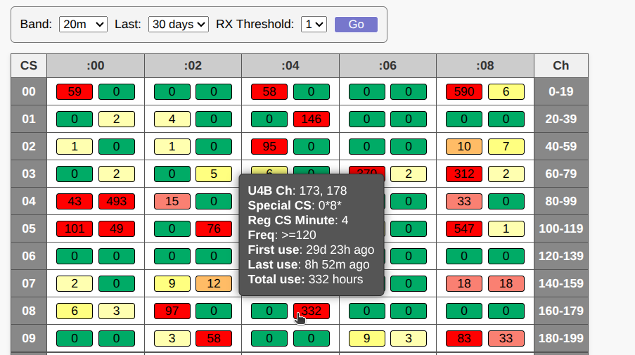
In the table, the columns represent the starting minute of the regular callsign transmission, while the rows correspond to the first and third characters of the special callsign (such as Q1 in QB1ERZ). Each cell contains two colored buckets, and each bucket in turn represents two U4B channels in adjacent frequency lanes (i.e. one bucket covers 0-80 Hz while the other 120-200 Hz). Binning of nearby channels is necessary because RX frequency errors can easily exceed the 40 Hz width of a single U4B channel.
The rightmost column of the table displays the range of U4B channels for each row. To locate a specific U4B channel, first identify the row containing the range, then scan across that row to find the channel.
The number in each bucket indicates how many unique 1-hour slots contained standard telemetry for that channel during the specified period (custom telemetry is excluded). For a slot to be counted, at least two standard telemetry transmissions must occur within the hour. This threshold helps eliminate noise caused by corrupt messages, non-U4B use of special Q/0/1 callsigns, and various other corner cases.
Additionally, an RX Threshold setting is available to
filter out single-receiver reports when set to 2. Standard telemetry
reported by only one receiver is more likely to have an inaccurate
frequency, as frequency values are averaged across multiple receivers.
In some cases, single-receiver reports are also associated with
incorrectly set receiver clocks, which can result in telemetry being
assigned to the wrong time slot.
Buckets are color-coded based on their count: green indicates that no standard telemetry has been observed in any 1-hour slots, while red represents multiple hours of daily use over an extended period. For example, a tracker that transmits for 10 hours every day will show a count of about 300 after 30 days. Yellow and orange fall in between, with yellow in particular sometimes reflecting leakage from a nearby busy channel due to RX frequency errors.
While the map may display some false positives, it is highly sensitive to channel activity and should therefore produce virtually no false negatives. A transmitter operating for as little as 20 minutes and detected by a single receiver will change a bucket’s color from green to yellow.
This makes the map potentially suitable as a robust reservation mechanism for U4B channels. Below is a proposed procedure for reserving a U4B channel using the map:
- Set the time range to 30 days and set
TX Thresholdto 1. - Select a random green bucket (or better yet, a cell containing two green buckets).
- If you already have an active tracker using your callsign, ensure the new bucket has a different starting minute. In other words, you cannot have two trackers in the same column of the table.
- The green bucket will show 2 U4B channels, with the preferred channel -- the one that is farther away from the adjacent bucket -- highlighted with an asterisk (*).
- Program the selected channel into your tracker and launch it. The bucket should turn from green to yellow shortly afterward, signaling to others that the channel is now in use.
- If you’re not ready to launch yet, but want to reserve the channel, perform a few test transmissions. You can self-report using an SDR dongle with WSJT-X or WsprDaemon software. This will mark the channel as active for the next 30 days.
- After a tracker stops transmitting, the channel will automatically revert to green after 30 days.
Note that this is just a proposal at this time. You should not use the channel map for reservations unless your only alternative is selecting a channel at random.
License
WSPR TV is licensed under the AGPL-3.0 license and can be used freely as long as the license conditions are met. In particular, the license requires that:
- If any part of your project is derived from WSPR TV in any way, your entire project must also be licensed under AGPL-3.0.
- All components of your project must be AGPL-3.0 compatible. For example, you cannot use MapBox JS mapping libraries because those are only available under proprietary licenses in recent releases.
- Proper attribution to WSPR TV must be provided both in your source code and in the UI. In the source code, you must clearly state what code was used and how it was modified. All copyright and license notices must be preserved.
WSPR Live, which is used by WSPR TV, has additional requirements in its disclaimer:
You are allowed to use the services provided on wspr.live for your own reasearch and projects, as long as the results are accessible free of charge for everyone. You are not allowed to use this service for any commercial or profit oriented use cases. The complete wspr infrastructure is maintained by volunteers in their spare time, so there are no guarantees on correctness, availability or stability of this service.
The source code for WSPR TV is available on GitHub.